ChemCam (Figure 5) consists of the first active remote sensing spectroscopy instrument for Mars (LIBS), along with a telescopic remote micro-imager (RMI) yielding the highest resolution images to date of objects greater than two meters from the rover. In the LIBS technique, laser pulses are focused onto a sample. At sufficient power densities, that is, at more than 10 megawatts per square millimeter (the energy of one million light bulbs focused on a spot a little bigger than a pinhole), atoms are ablated in excited states, and emit light (a “spark”). The composition is then determined by spectrally resolving the emission lines characteristic of the elements present, and calibrating them. The RMI provides very high resolution images of targets within about 10 meters of the rover. Resolution in the near-field is 2-3 times coarser than the MER micro-imager, but still sufficient to see many diagnostic sedimentary structures and other features at the sub-millimeter scale.
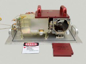
of spacecraft instruments are nearly identical to their flight model counterparts. Credit: ChemCam/LANL/IRAP/CNES
ChemCam Operation Sequence The typical ChemCam operation sequence is outlined in Figure 6. The instrument is pointed using the elevation and tilt of the mast platform. Targets are identified based on NavCam images. ChemCam operational steps are as follows:
- Thermo-electric cooler (TEC) is turned on to cool the detectors.
- Functional Self-Test: an aliveness test initiated at the beginning of every ChemCam turn-on. It can be executed during the cruise and right after the first instrument turn-on following landing. This mode sets all sub-systems in their default mode and checks basic interfaces between subsystems.
- Laser warm-up: The laser operates best at -10° to 0° C. Normally the box holding the laser is at -40° C. Up to 15 minutes are needed to warm the laser before operations. The focus laser (continuous-wave laser, or CWL) is also warmed up.
- Focusing: A laser pointer is turned on, illuminating the target with monochromatic light. The focus stage is scanned while the signal is monitored at the correct wavelength by a detector. The signal is checked for saturation, repeating the scan with less sensitivity if necessary. The focus position is determined by the maximum in the fitted data.
- RMI Imaging: The imager software inherited from Rosetta includes autoexposure algorithms, with typically four different exposures made, and the best image is kept. For a typical rock analysis scenario a full 1024×1024 pixel image is taken prior to LIBS analysis, and an image of only the analysis spot (e.g., 128×128) is taken subsequent to analysis. While LIBS and RMI will be used frequently together, there will be numerous times when RMI will be used separately, such as to provide close-up images to support arm-mounted experiments, or provide images of very distant objects.
- LIBS Data Acquisition: The laser is fired in a rapid series of shots while the spectrometer collects spectra. The laser can operate at 1-10 Hertz, with a nominal repetition rate of 3 Hertz (shots per second).
- Post-LIBS Image: Typically, an image of the laser spot will be taken subsequent to LIBS analysis, as mentioned above.
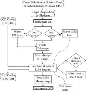
Not counting warm-up, each analysis will take approximately six minutes.
The ChemCam Instrument Suite As shown in the block diagram (Figure 7), the suite consists of two boxes: the Mast portion contains the telescope, laser, remote micro-imager (RMI), and front-end electronics, while the Body portion contains three spectrometers, a demulitplexer, a thermo-electric cooler, a data processing unit, power supplies, and a rover interface.
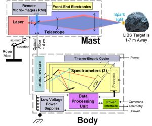
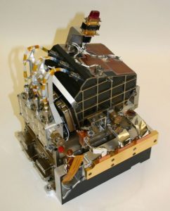
The Mast Unit The Mast Unit (Figure 8) focuses on a target, generates a series of laser pulses, and collects light for the LIBS analysis. It also takes images with the RMI. It is mounted atop the MSL mast to benefit from the mast’s pointing capability. The Mast Unit is divided into four subsystems: the laser, the telescope, the camera, and the electronics box.

Laser The LIBS technique requires a pulsed laser delivering at least 10 megawatts per square millimeter to the target. Implementation of this is a trade-off between telescope and laser capabilities, as described below. The requirement is met with a low-frequency (1-10 Hertz) laser of moderate beam quality (M2 is less than 3) and pulse duration less than 5 nanoseconds using greater than 10 milliJoules of energy per pulse. Any wavelength in the visible or near-IR suffices, but lasers with wavelengths approximately 1 micron are simplest and most common for the above capabilities. The ChemCam laser uses a Nd:KGW crystal to produce light at 1.067 microns.
Telescope The telescope is required to 1) concentrate the laser beam onto the target, 2) collect laser-induced plasma light, and 3) obtain the image for the RMI. With external conditions set by the laser, camera, and spectrometer optical characteristics, the main functional requirements are:
- For (1), deliver greater than 10 megawatts per square millimeter to targets 1.5-7 meters distant. With moderate laser powers this requires focus capability to ±1% accuracy.
- For (2), collect plasma light from 240-850 nanometers within a 300 micron optical fiber.
- For (3), divert maximum ambient light to a camera with a field of view of 20 centimeters at 10 meters and a resolution of 0.1 milliradians.
The telescope is a simple and compact Schmidt-Cassegrain, with a fixed primary mirror and a moving secondary mirror used to focus. As shown in the figure, the laser beam is expanded by 10x. The 110 millimeter diameter primary mirror collects return light, which is focused into the optical fiber for LIBS and onto the RMI CCD.
Remote Micro-Imager (RMI) The heart of the RMI instrument is the flight qualified CCD and associated electronics which were developed for Smart-1, Rosetta, and Mars Express. The 1024 x 1024 pixel CCD has been qualified to an operating temperature range of -120 to +30ºC, and a survival range of -150 to +50ºC. In the flight-qualified set-up, it consumes 1.5 W, and has 10 bit/pixel resolution. The software allows exposure times between 2 milliseconds and 8 seconds, and has an algorithm for auto-selecting exposure times by taking images at four different exposure times and selecting the image that minimizes saturation and maximizes the pixels with greater than 25% of the dynamic range.
Mast Electronics The mast electronics box contains all front-end electronics (FEE) for the LIBS laser, focus laser stage, micro-imager, and focus stage. The RMI front-end electronics are monolithically integrated directly with the CCD in a 100 gram package.
Body Unit Seen in Figure 9, the Body Unit contains an optical demultiplexer, three spectrometers, a data processing unit (DPU), a power buffer, and rover interface. Each of these components is described below.
Spectrometers The ChemCam spectrometers consist of three separate units covering separate spectral ranges. Each spectrometer unit is a modified version of Ocean Optics, Inc. commercial model HR2000. The three ranges are 240-336 nanometers, 380-470 nanometers, and 470-850 nanometers, designed to meet the spectral resolution and range requirements. A fiber optic cable is used to bring light from the telescope to a demultiplexer, which splits the light into three spectral ranges for the spectrometer, optimizing the amount of light sent to each spectrometer. The cabling is described below in the next section. The three spectrometers are nearly identical, with the exception of different gratings and mirror coatings. The use of three nearly identical units greatly simplifies the design, while providing a significant degree of redundancy, because many elements have spectral lines in more than one of the spectral ranges covered by the three units.
Fiber and Other Cabling Cabling between the Mast and Body Units consists of a) a digital line between the DPU and the Mast front-end electronics box, b) a dedicated line between the RMI front-end electronics and the DPU, c) a line providing unregulated power, and d) a fiber optic cable providing LIBS light to the spectrometers. The fiber has a fused silica single-core 300 microns in diameter.
DPU and Interface Circuit The ChemCam Body Unit contains an electronics box with a power supply board at the bottom, two DPU boards, and two boards for the spectrometer functions. The DPU is in full control of the entire ChemCam at all times as dictated by mission commands, and performs the following functions: 1) to accept, store and decode commands, 2) to configure all subsystems, 3) to control operational modes (focusing the optics, taking images, firing of the pulsed laser, reading the data from the spectrometers and imager), 4) to process and compress the image and spectral data to transfer to the Rover Computer, and 5) to collect and process narrow band status (State of Health) data.
Power Supply The power supply generates a set of fully isolated outputs of various voltages and currents for the ChemCam body unit.